9/11 WTC 2 Aircraft Impact Orientation (Draft)
The intention of this
document is to determine the fuselage impact orientation and nose-to-tail
impact trajectory of the aircraft that crashed into WTC 2 on 9/11, and to document
the methods used to derive the orientation and trajectory values.
Throughout all steps of this
method, the corresponding values used by NIST within their computer simulations
and impact damage assessment studies will be included, and any differences
highlighted.
This method intimately
combines accurate 3D models of the aircraft and buildings with photographs and
video of the actual event to produce self-validating visualisations of all
orientation values.
The rotoscoping of virtual
3D models over actual photographic and video evidence of the real event is an
inherent part of this method, and provides an additional level of validation
not yet presented within other methods, such as those used by NIST.
Digital resources utilised
will be made available via links in the appendix to allow full personal
validation of all enclosed details, measurements and values.
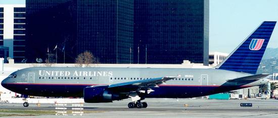
The Aircraft
The aircraft which impacted
WTC 2 was identified as a long-range version of the Boeing 767-200,
specifically a Boeing 767-222/ER.
Basic Scale Specification
Length 48.5m 159ft 2in
Wingspan 47.6m 156ft
1in
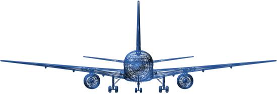
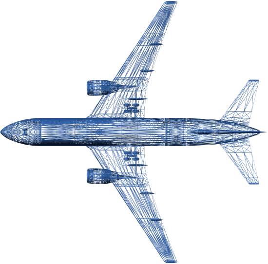
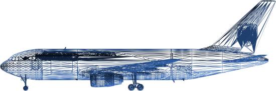
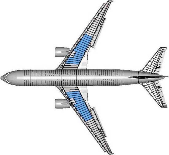
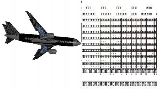
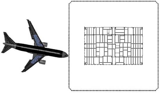
The 3D Aircraft Model
The 3D model used is a
public-domain rendition of the Boeing 767-200, sourced from the Google SketchUp
directory, which has been converted into 3DS format and is specifically scaled
in world coordinates. The world coordinate system used is 1ft=1unit. Primary
dimension scaling, such as aircraft wing-span, is accurate to within 1 inch.
Sub-feature scaling is accurate to much greater precision, relative to the
scaling of primary dimensions. Accuracy of the model is more than reasonable
for the purposes of this method.
Comparison to the NIST 3D Aircraft Model
The identified aircraft
(Flight 175 – UAL175)
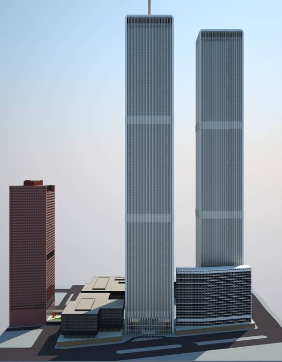
The Buildings
World Trade Centre Complex
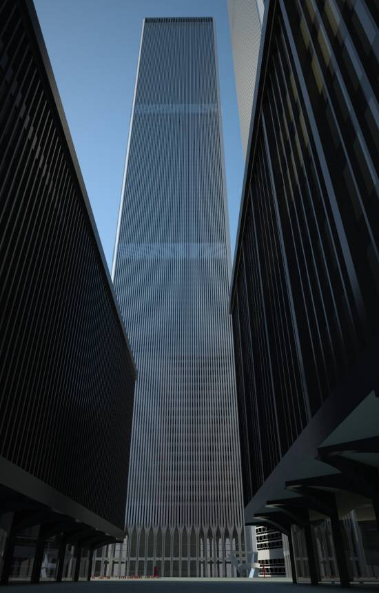
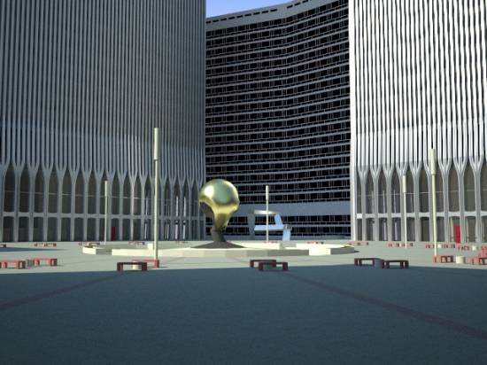
A correctly scaled and very
detailed public-domain model of the WTC Complex is used for all three
dimensional rotoscoping tasks.
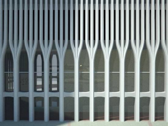
The following images show
the accuracy and detail of the model in an artistic sense, followed by specific
comparison between the model and technical diagrams used by NIST.
(Add more images)
Note the accuracy in
alignment between the tower external columns, spandrel plates and corner
construction elements.
Alignment Methods
The first method of
alignment used is the definition of the specific extremities of the aircraft
impact damage outline, which can be determined by inspection of photographic
and video evidence.
Three ‘control points’ are
defined:
1) The port (left) wing-tip façade penetration point.
2) The starboard (right) wing-tip façade penetration
point.
3) The nose-cone impact point.
Any derived orientation and
trajectory must result in the nose-cone making contact at the nose-cone
impact point, the port wing-tip penetrating the façade at the port wing-tip
penetration point and the starboard wing-tip penetrating the façade at the
starboard wing-tip penetration point.
These three simple defined
points strictly limit the orientation and trajectory possibilities.
Any orientation and
trajectory that does not adhere to these control points, within reasonable
errors of margin, cannot be correct.
The second method of
alignment is the rotoscoping of a virtual three-dimensional environment upon
photographic and video evidence of the physical event.
Placement of the footage
camera is determined and all appropriate viewport perspective parameters are
adjusted to ensure maximum match quality between virtual and real views. Due to
the limitations and implications of perspective and aperture adjustments
available in the version of 3D studio I have available, the virtual camera
placement cannot be exactly ‘on’ the defined real-world camera position, but is
behind and below it. It is however ‘in-line’. This will be shown to provide
accurate angular referencing between virtual object placement and real-world
imagery, with angular resolution accuracy increasing as the distance between
the real-world camera location and the ‘target’ (WTC2 in this case) increases.
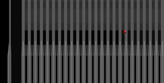
Control Points
Port Wing-Tip
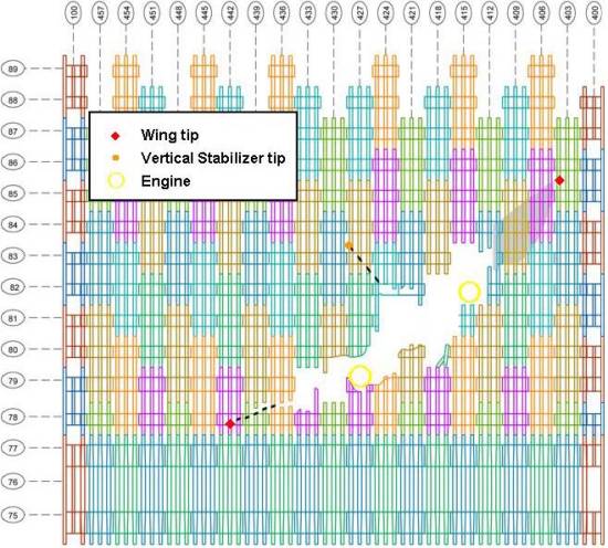
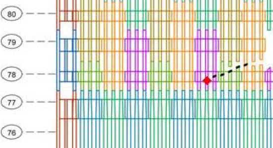
The NIST point placement is
mid-way across column 442, at the bottom of the 78th floor spandrel
plate.
This study will define the
point as being at the following location:
- Left hand edge of column 442.
- One half column width below 78th
floor spandrel plate.
- The margin of error will be defined as +/- half
the width of one column, both horizontally and vertically.
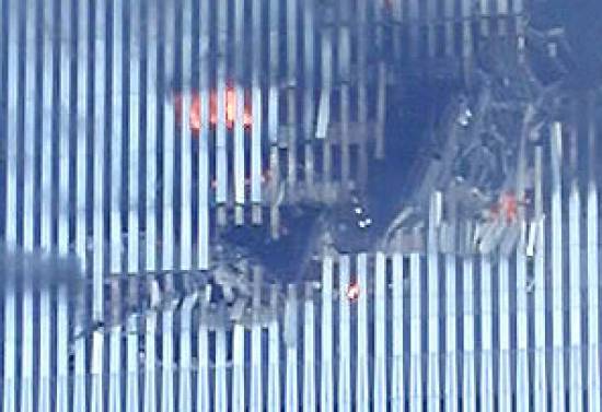
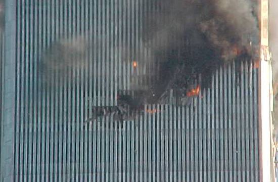
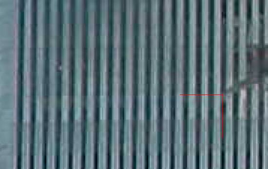
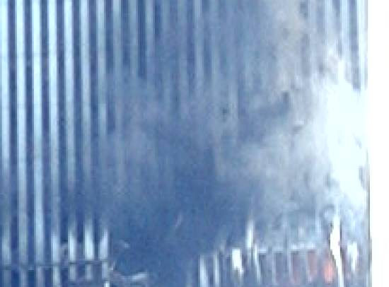
Starboard Wing-Tip
Due to the lack of
high-resolution photographs of the starboard wing-tip penetration point that
are not obscured by smoke, the accuracy of the penetration point position is
lower than for the Port wing-tip. The reduction in positional quality is
indicated by an increase in Control Point marker size in the virtual model.

NIST Point placement is on
the right hand edge of column 404, mid-way between the inter-spandrel plate
space separating floors 85 and 86.
This study will define the
point as being:
- In the middle of column 405 (Three intact
columns are visible in the photographs included above)
- Mid-way between the inter-spandrel plate space
separating floors 85 and 86.
- The margin of error will be defined as +/- 3ft,
both horizontally and vertically, with emphasis placed towards –ve
horizontal adjustment being the more probable correct value.
Nose-Cone
Sources to determine
nose-cone impact position are clearly limited to video footage.
NIST Nose Impact Point Placement
NIST point placement is at
the top of the 81st floor spandrel plate, and in the middle of column
423.
Here is that point placed on
the 3D building model:
Accurate placement of the
nose-cone impact point will be undertaken in conjunction with building model
rotoscoping.
Definition will be conducted
a little later in this document, after camera location of the video footage has
been documented, and viewpoint orientation and perspective has been determined.
This will allow for more accurate definition of the control point.
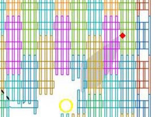
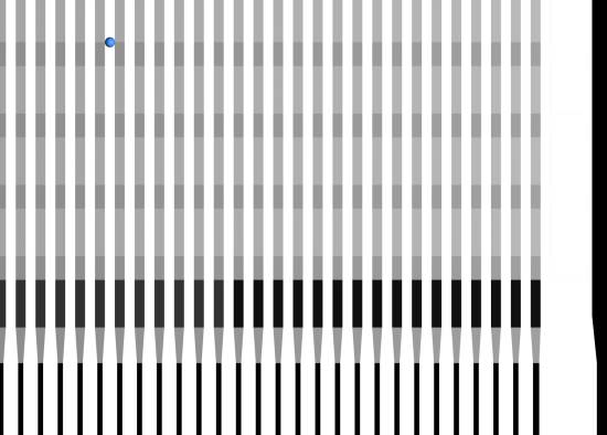
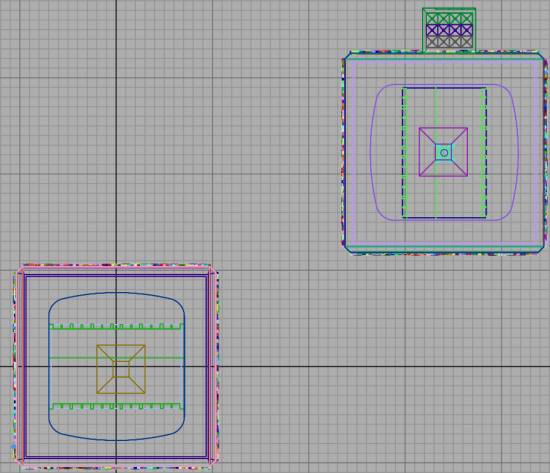
Virtual Building Positioning
WTC Complex
Purely to increase rendering
performance, buildings in the full WTC complex base model other than WTC1 and
WTC2 have been removed.
WTC 1 and 2 relative
positioning is fully retained, positioned such that the coordinate of the
centre-point of WTC 2 footprint is at (0,0).
The grid shown is in 10ft
units.
Additional Buildings
Google Earth/Sketchup models
of additional buildings present in the video footage being rotoscoped have been
converted to 3DS format and imported into the environment.
As 3D building placement and
scaling within Google Earth is not exact, placement of each building has been
performed with reference to the underlying satellite photography available
within Google Earth, and each model individually scaled according to published
building heights. Further refinement of these models is required to fully
finalise this method, however every care has been made to ensure the placement
is as accurate as possible.
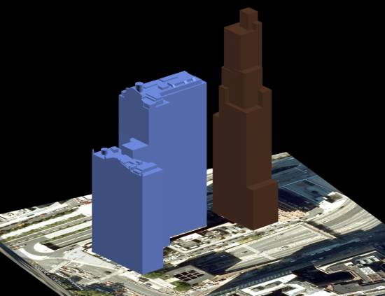
Downtown Athletic Club
Height – 162.8m / 534ft (Source)
Whitehall Building
Height – 129.24m / 424ft (Source)
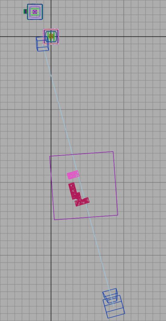
Geometry placement
The following overview shows
the relative placement of ‘scene’ elements, including WTC1, WTC2, Downtown Athletic Club, Whitehall Building
and Camera.
The grid shown is in 100ft
units.
The blue cube near to WTC2
SW corner represents to camera ‘target’.
A Quick Look at the NIST Orientation
Before continuing, it is
prudent to highlight the most fundamental issue with the NIST impact
orientation values.
The following table contains
the trajectory and orientation data that NIST based their impact simulations
upon:
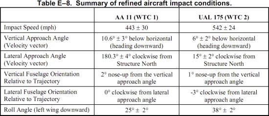
The Lateral Approach Angle
and Lateral Fuselage Orientation values are a significant focus of this study.
The simplest way to begin is
to look at the relative portion of the starboard (right) wing which has not
penetrated the façade at the point in time that the port (left) wing tip
penetrates the façade. Several video clips include enough detail to highlight
this metric, and two will be referenced here.
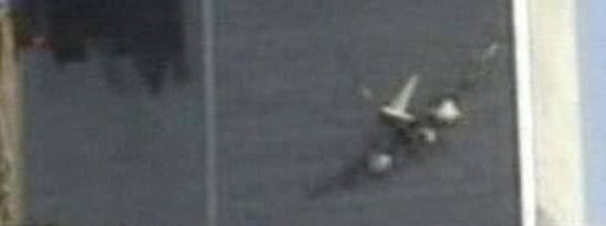
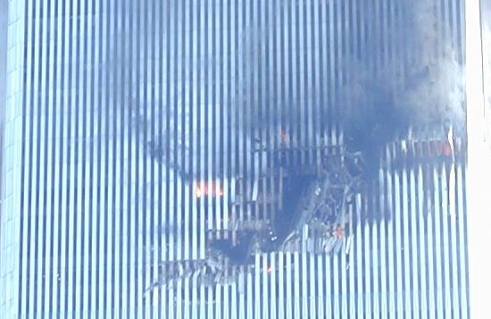
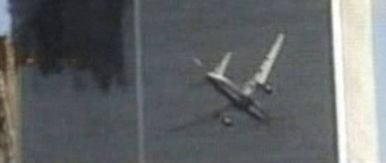
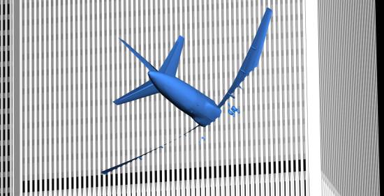
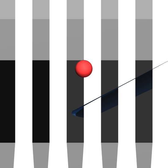
This still frame is taken as
near to the point in time that the port wing tip penetrates the façade as
footage allows:
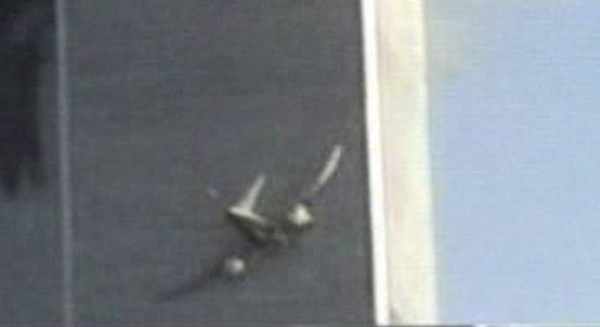
Note the portion of the
starboard wing that has not yet penetrated the façade, and the
length/orientation of the remaining fuselage segment.
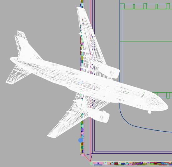
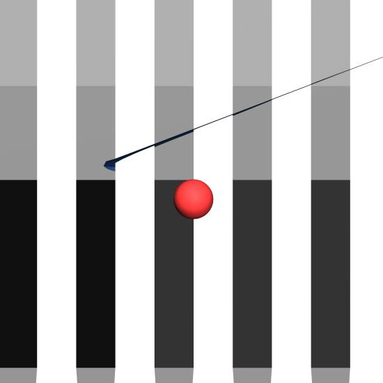
Compare it with this virtual
render, which has the aircraft set to the base NIST orientation (NCSTAR2 E-23):
(We have not yet fully
defined the video rotoscoping, and it is not suggested that the virtual camera
perspective illustrated is spot-on. In the context here that is irrelevant, as
we are looking at relative feature proportions.)
If the problem is not
obvious enough (viewing angle really does make a big difference)
cross-referencing with another well-known clip may help…
It does of course require
careful inspection to see the problem, which can be summarised as being that,
at the point in time that the port wing-tip penetrates the façade, in the
actual footage a maximum of one half of the starboard wing width is visible,
with the other half having already entered. Whereas in the virtual render (in
which viewing angle is totally irrelevant) the full width of the wing has not
yet penetrated the façade and even the wing root is still visible.
Take some time to compare
the actual footage with a rendered view of the impact with the NIST base
orientation:
Whilst you may think that
the difference is not extreme, it will be shown later that the resultant effect
of orientation and trajectory changes upon potential damage inside the building
is highly significant.
When the video rotoscoping
is performed, the orientation differences are further highlighted.
Aircraft Dihedral Wing Angle
Even in normal flight,
forces upon the aircraft airframe result in ‘bending’ and flexing of the wings.
When performing increased ‘G’ manoeuvres, the amount of wing flexing increases.
The resulting change in
dihedral wing angle must be taken into account when determining the impact
orientation, as change in this angle affects the position of the wing-tips relative
to the nose-cone, and also results in very slight narrowing of the ‘plan-view’
wing-span as the angle increases.
NIST Representation of Wing Deflection
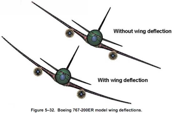
Aircraft Model Representation of Wing Deflection
A similar, but very simple,
process is also applied to the aircraft model in this study, namely a simple
‘bend’ modifier applied to the aircraft:
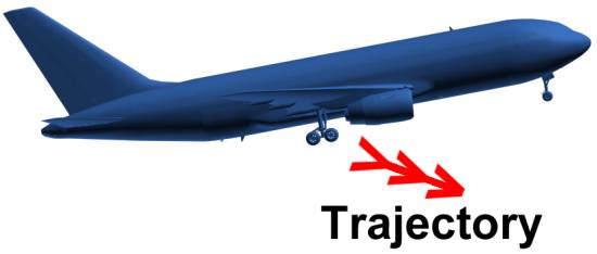
The Importance of
treating Trajectory separately from Orientation
NIST specify trajectory and
orientation separately, but appear to have combined the two axis values
together within their simulations.
“The aircraft and exterior wall models were used to visualise the impact scenario in the figures and the view shown was aligned with the aircraft trajectory.” NCSTAR1-2 E.6
The simplest way to understand
the need to treat them separately is to visualise the behaviour of an aircraft
whilst landing, in which the orientation is inclined at a significant angle,
whilst the direction of vertical travel is in entirely the opposite direction:
Another look at the base NIST Orientation
We now have the wing-tip
penetration points defined, and the NIST nose-cone impact point.
This provides enough
information to test the NIST base impact orientation values (Which they align
to trajectory).
Do the base NIST values
result in the wing-tips passing through the control points ?
Port Wing Without Deflection:
Port Wing with 10 degree
Deflection:
Port wing-tip penetration
with the NIST base values is significantly off, both with and without
deflection.
Starboard Wing with No
Deflection:
Starboard Wing with 10
degree Deflection:
Starboard wing-tip
penetration point accuracy is pretty much spot-on with deflection, and also fairly
reasonable without deflection.
HOWEVER, it has already been
shown, by looking at relative amounts of the wing that have penetrated the
façade, that the horizontal angle is incorrect.
This point will be
emphasised and made clearer when the rotoscoping is performed.
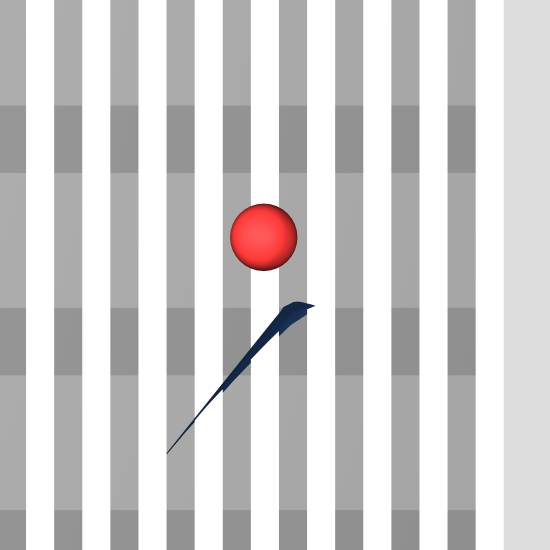
Sample rotoscope, using a
non-final camera location (Orientation: NIST 6,38,13)

Anything seem to be amiss
here ? The rendered aircraft looks enourmous.
However, please note that if
both the vertical and horizontal angles were different, then this apparent
‘bizarre’ view is then clarified…
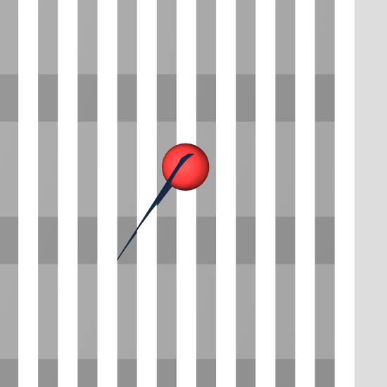
Sample rotoscope, using non-final camera location (Orientation: TEST 3,37,3.5)
Much better. Not perfect
yet, but a lot closer to matching the footage than the NIST orientation.
Please remember that there
is no change to the size of the aircraft at any point in time.
Even though the camera
viewpoint is non-final, it is clear, even at this point, that the NIST
orientation is significantly incorrect.
The difference between the
orientation angles above is quite marked, with a difference of 3 degrees
vertical and a massive 9.5 degrees horizontal.
As you can see, using the
video rotoscoping method provides an additional mechanism to validate orientation.
The base NIST orientation
seems to be a good match for the starboard wing penetration point.
The base NIST orientation
seems to be a dubious match for the port wing penetration point.
The base NIST orientation
viewed from a rotoscoping perspective is atrocious, and has serious and
far-ranging implications for NIST’s subsequent impact damage analyses.
The rest of this study will
focus upon increasing the accuracy of the nose-cone impact location, the
correct aircraft orientation and trajectory, and the rotoscoping camera
viewpoint.
I will upload “part 2” as
soon as possible. This version is for comment within the911forum only, and does
not constitute an ‘official’ release.
Regards,
Femr2